
Do you remembering my magic H0 train moving with no cables on the tracks? See my old blog entry…


I did it again, but now with use of an ultra small evaluation platform called ClickBeetle so I could minimize the result from H0 into a n-track sized wagon.

The concept is slightly different to my first H0-track wagon central, since the H0 version is running a complete Linux on RaspberryPI Zero W with Rocrail and SCPD while the N-track wagon central is having a Cortex M4 micro controller with much less power consumption.
I made use of the BlueBeetle1 to have MCU and a BLE connection to my iPhone.
The ClickBeetle BlueBeetle1 is using:
- Ambiq Micro Apollo1 MCU
- Nordic nRF8001 BLE
I’ve also added a 16mm x 26mm small board in ClickBeetle form factor footprint with power-conversion and H-bridge IC. I called my own shield board “InverterBeetle”.


InverterBeetle has following parts:
- SOT-23-5 LDO 3.3V (for example TS5205)
- Step-up converter to 14V (LT1935)
- Motor Driver / H-Bridge DRV8871
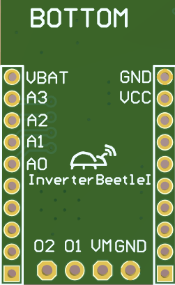
PCB


Schematic
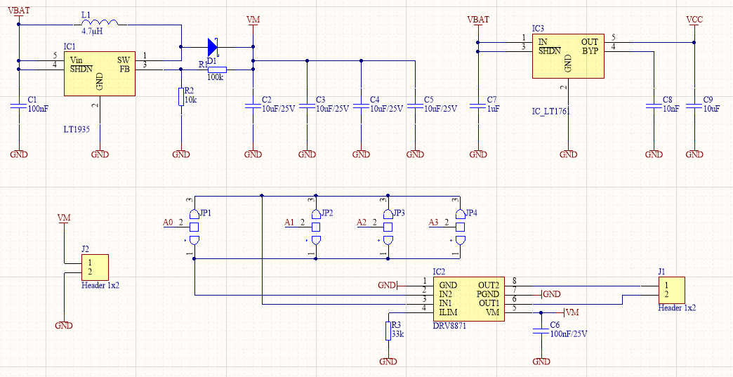
The power supply VCC for ClickBeetle was done via a simple LDO converting the VBAT to 3.3V (and lower). A step-up converter LT1935 is configured to generate 14V of an input between 2.3 and 16V. A voltage between 14 and 16V is needed for the DCC signal, driven by the DRV8871 single DC motor bridge.
It is possible to connect a LiFePo4 battery or LiPo battery.
BlueBeetle1 works in a voltage range between 2.2V and 3.65V.
If used with LiFePo4, the power range of the battery is between 2.0 and 3.65V and the LDO should be replaced by a short-cut between VBAT and VCC. Anyhow the step-up converter works from 2.3V only, so the usable voltage range is just 2.3 – 3.65V.
If used with LiPo, the VBAT power range is with one cell between 3.0 and 4.2V. The LDO has a voltage drop of about 1V. So for LiPo battery the usable voltage is between 3.2V and 4.2V if BlueBeetle1 works down-to 2.2V and the LDO voltage drop is minimum 1V.
If used with a dual cell LiPo battery, the VBAT power range is between 6.0V and 8.4V and can be used in the full voltage range. So best fit is a dual cell LiPo battery (2S LiPo battery).
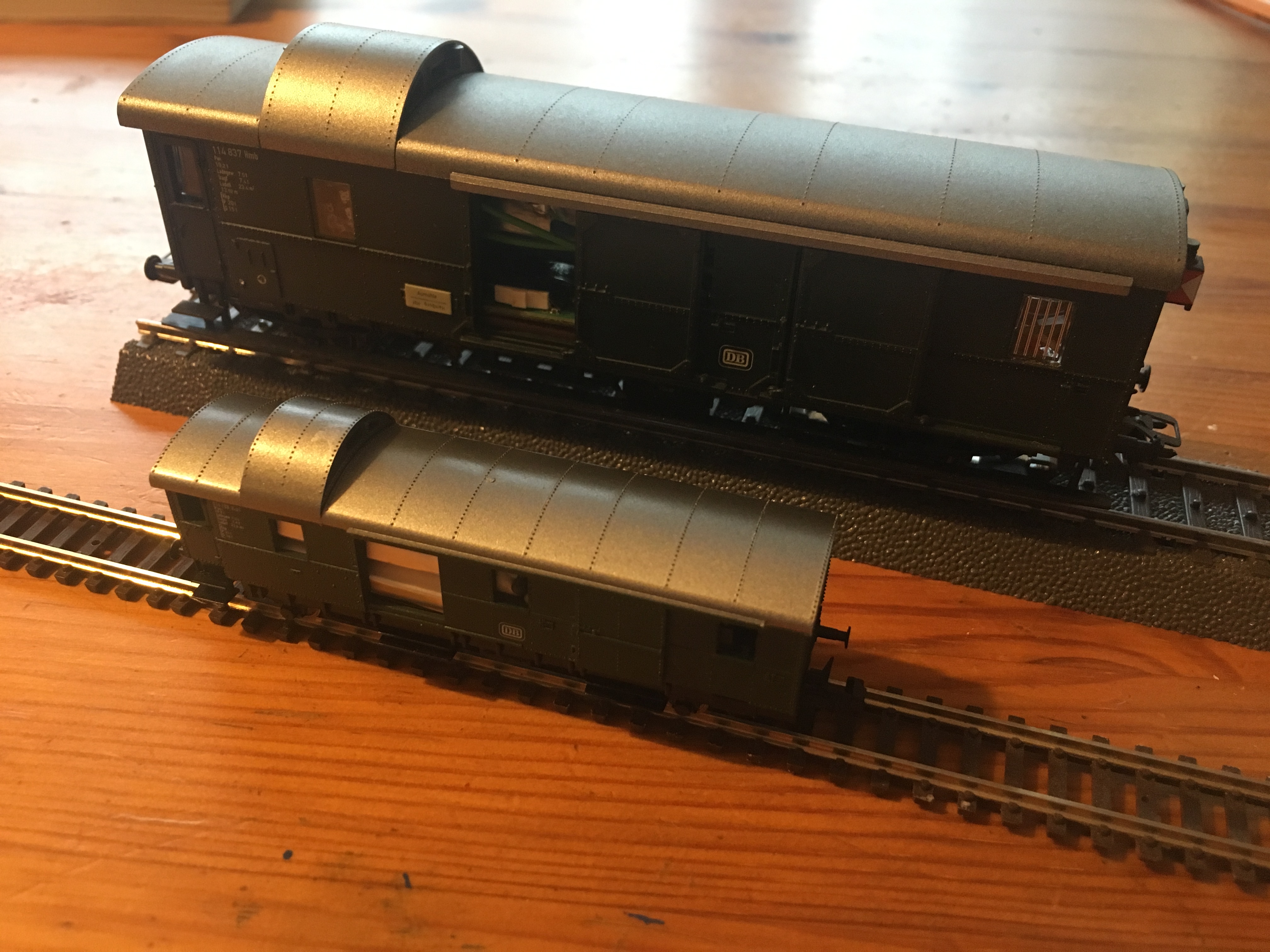
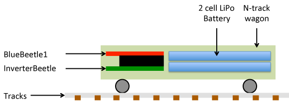
Putting BlueBeete1, InverterBeetle and the 2S LiPo battery together in a n-track wagon looks like following graphic:
Firmware
The firmware uses Nordic’s BLE SDK for Arduino https://github.com/NordicSemiconductor/ble-sdk-arduino and is based on the UART example.
BLE Protocol
There are up to 20 bytes per message available, so the protocol looks like that:
BLE Central (iPhone) -> BLE Peripheral (BlueBeetle1)
String Data:
| <addr> set speed <xxx> example: 3 set speed 24 |
loc address <addr>=1..127 speed <xxx>=-127 … 127 |
| <addr> set func F<n> <0/1> example 3 set func F0 1 |
loc address <addr>=1..127 function <n>=0…28 <0/1>=0 on, 1 off |
BLE Peripheral (BlueBeetle1) -> BLE Central (iPhone)
Binary Data:
<uint8 const=0><uint8 addr><int8 speed><uint32 functions>
first byte is 0
second byte is the loc address
third byte is speed as int8
the next 4 bytes are a little endian uint32 containing a bitfield of F0…28
Bit timing DCC
The DCC generation needs an interrupt driven every 58us. The MCU used with BlueBeetle1 is Apollo1 of Ambiq Micro. This MCU has one timer that can drive up to 8 sub-timer units. In the following example the CTIMER unit 0B is used to generate the 58us interrupt.
/**
*****************************************************************************
**
**\brief Init Timer for 58us interval IRQ generation
**
*****************************************************************************/
void DccGeneration_InitHw()
{
ApolloGpio_GpioOutputEnable(CLICKBEETLE_A0,TRUE);
ApolloGpio_GpioOutputEnable(CLICKBEETLE_A1,TRUE);
CTIMER-&amp;gt;INTEN = 0;
CTIMER-&amp;gt;CTRL0_b.TMRB0CLR = 1; //clear timer B
CTIMER-&amp;gt;CTRL0_b.TMRB0PE = 1; //enable output timer B
CTIMER-&amp;gt;CTRL0_b.TMRB0IE = 1; //enable IRQ timer B
CTIMER-&amp;gt;CTRL0_b.TMRB0FN = 3; //repeated pulse count timer B
CTIMER-&amp;gt;CTRL0_b.TMRB0CLK = 0x01; //HFRC = 24MHz
//Interval 58us = 58/1000000
//PWM Cycle = 24MHz * 58/1000000
//PWM Duty = PWM Cycle / 2
CTIMER-&amp;gt;CMPRB0_b.CMPR0B0 = 58*24000000UL/1000000UL/2; //PWM Duty
CTIMER-&amp;gt;CMPRB0_b.CMPR1B0 = 58*24000000UL/1000000UL; //PWM Cycle
CTIMER-&amp;gt;INTEN_b.CTMRB0INT = 1; //enable interrupt for compare value 0
NVIC_ClearPendingIRQ(CTIMER_IRQn); //clear pending flag for CTIMER
NVIC_EnableIRQ(CTIMER_IRQn); //enable CTIMER IRQ
NVIC_SetPriority(CTIMER_IRQn,1); //set priority of CTIMER IRQ, smaller value means higher priority
CTIMER-&amp;gt;CTRL0_b.TMRB0CLR = 0; //release clear timer B
CTIMER-&amp;gt;CTRL0_b.TMRB0EN = 1;
}
/**
*****************************************************************************
**
**\brief 58us Interrupt Service Routine
**
*****************************************************************************/
void CTIMER_IRQHandler(void)
{
if (CTIMER-&amp;gt;INTSTAT_b.CTMRB0INT == 1)
{
CTIMER-&amp;gt;INTCLR_b.CTMRB0INT = 1;
DccGen_Update58usInterval(); //update the DCC statemachine
}
}
iOS App
The iOS App has an icon of a Köf II as front view.

Opening the app gives access to all functions, loc address setup and a speed slider.
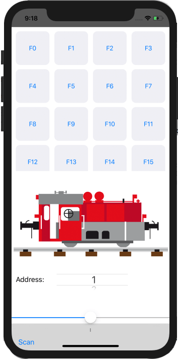
Before the app can be used the “Scan” button on the left lower corner has to be tapped to scan for the BLE peripheral.
More information will follow soon including iOS App Source and Embedded Firmware.